How to Build a LiFePO4 Battery for a Hybrid Inverter
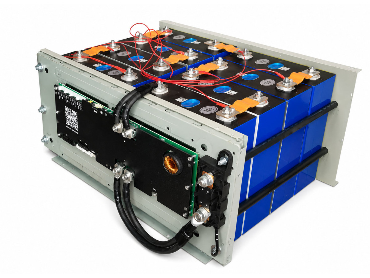
LiFePO4 batteries are widely used with hybrid and off-grid inverters in backup power systems. Individual prismatic cells can be assembled into a battery with the required voltage and capacity, equipped with a BMS, and used as a complete energy storage system.
However, building a LiFePO4 battery involves much more than simply connecting several cells in series. The cells must be positioned correctly, securely connected with busbars, connected to the BMS, equipped with temperature sensors and power wiring, and the entire system must be checked before connecting it to the inverter.
Let us examine the entire process in detail.
Important: LiFePO4 batteries can deliver extremely high short-circuit currents. Assembly errors, accidental short circuits caused by tools, or incorrect BMS connections can damage equipment, cause severe conductor heating, and create a fire hazard. This work should only be performed by people with the appropriate knowledge and skills.
What You Need to Build a LiFePO4 Battery
The battery is based on prismatic LiFePO4 cells.
You will also need:
a suitable BMS;
connecting busbars;
hardware for the cell terminals;
power cables;
cable lugs;
BMS balance wires;
temperature sensors;
protective devices;
power terminals or connectors;
insulating materials;
an enclosure;
components for mechanically securing the cells.
A multimeter will also be required for testing.
It will be needed at almost every stage of the assembly.
Checking the LiFePO4 Cells
Before connecting the cells, each one should be inspected and tested.
Visual Inspection
The cell cases should not have:
significant dents;
swelling;
damaged insulation;
traces of electrolyte;
damaged terminals;
damaged threads.
Particular attention should be paid to the positive and negative terminals.
Voltage Check
After the visual inspection, measure the voltage of each cell with a multimeter.
The nominal voltage of a LiFePO4 cell is approximately 3.2 V, although the actual value depends on its state of charge.
It is more important to compare the cells with one another.
If most cells have similar voltages while one differs significantly, that cell should be checked further before assembly.
Connecting LiFePO4 Cells in Series
To obtain the required battery voltage, the cells are connected in series.
The connection sequence is:
positive of the first cell → negative of the second → positive of the second → negative of the third → and so on.
With a series connection, the cell voltages are added together, while the capacity in amp-hours remains the same as that of a single cell.
For example, eight LiFePO4 cells connected in series form an 8S configuration.
If the nominal voltage of one cell is 3.2 V:
3.2 V × 8 = 25.6 V.
Therefore, an 8S LiFePO4 battery is a typical configuration for 24 V-class battery systems.
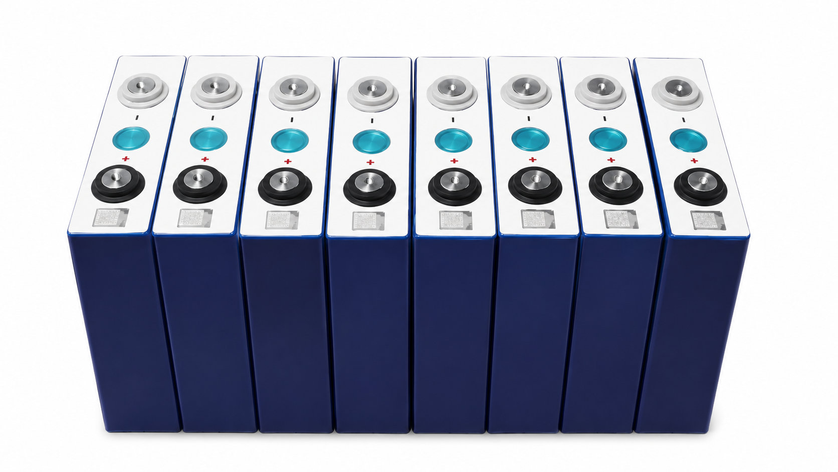
Before installing the busbars, always check the position of the positive and negative terminals.
An error in the connection sequence can cause a short circuit.
Installing the Busbars
Electrical connections between adjacent cells are made using metal busbars.
A busbar connects the positive terminal of one cell to the negative terminal of the next.
After all busbars have been installed, two end terminals remain free:
the battery positive terminal;
the battery negative terminal.
The full battery voltage will subsequently be present between these two terminals.
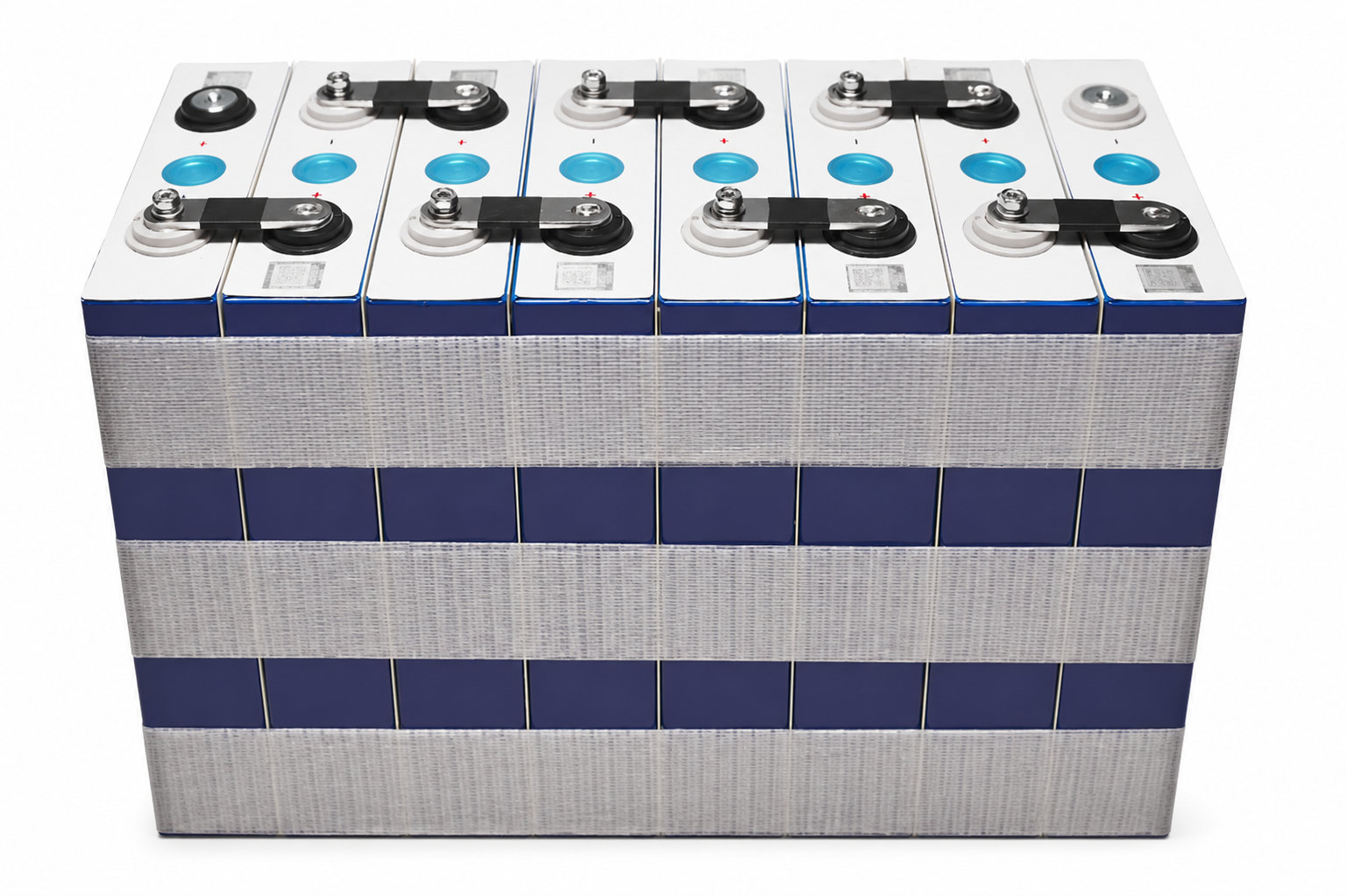
When working with battery cells, extreme care must be taken with metal tools.
Never allow a wrench, screwdriver, or other metal object to simultaneously touch two points at different electrical potentials.
Even a single LiFePO4 cell can deliver a very high short-circuit current.
Mechanical Securing of the Cells
Prismatic cells must be securely fixed in place.
After assembly, the cells should not be able to move freely relative to one another when the battery is transported or operated.
At the same time, the cell cases should not be excessively compressed.
Follow the recommendations of the specific cell manufacturer regarding installation and permissible compression.
Reliable electrical insulation must be provided between the battery cells, current-carrying parts, and any metal parts of the enclosure.
Checking the Voltage of the Assembled Battery
After installing the busbars, check the battery with a multimeter.
You can first measure the voltage of the individual cells again.
Then measure the voltage between the battery's main positive and main negative terminals.
For eight cells connected in series, each measuring approximately 3.2–3.3 V, the total battery voltage should be approximately 25–26 V.
The exact value depends on the state of charge.
If the measured voltage differs significantly from the expected value, stop the assembly process and check the connection sequence.
Installing the BMS
A BMS (Battery Management System) is used for proper and safe operation of a LiFePO4 battery.
The BMS monitors the condition of the battery and its individual cells.
Depending on the model, it may provide:
overcharge protection;
deep-discharge protection;
charging overcurrent protection;
discharge overcurrent protection;
short-circuit protection;
temperature monitoring;
cell balancing;
individual cell voltage monitoring;
state-of-charge calculation;
transmission of battery parameters to external devices.
The BMS must be selected according to the number of cells connected in series and the expected operating currents of the battery.
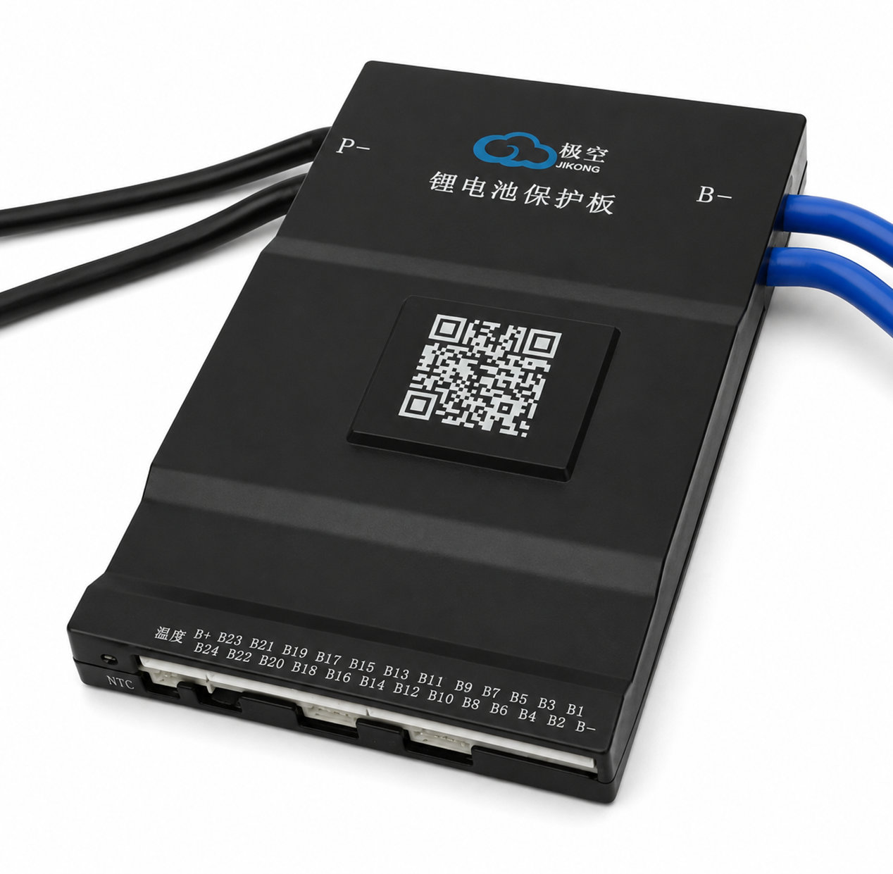
Connecting the BMS Balance Wires
The BMS must monitor the voltage of every cell individually.
For this purpose, a group of thin balance wires is used.
They are connected to the cell connection points in a strictly defined sequence.
A simplified connection sequence can be represented as follows:
B0 — main negative terminal of the battery pack;
B1 — positive terminal of the first cell;
B2 — positive terminal of the second cell;
B3 — positive terminal of the third cell;
and so on up to the final cell.
[PHOTO 5 — connecting the balance wires]
The connection sequence must be checked especially carefully.
Before plugging the balance connector into the BMS, it is advisable to verify the wiring with a multimeter.
When measuring relative to the main negative terminal, the voltage should increase step by step.
For an 8S battery, an approximate sequence may look like this:
3.2 V → 6.4 V → 9.6 V → 12.8 V → 16 V → 19.2 V → 22.4 V → 25.6 V.
The actual values depend on the voltage of the individual cells.
If the voltage does not increase as expected at any stage, check the wiring.
Only after verifying the balance wires should their connector be plugged into the BMS.
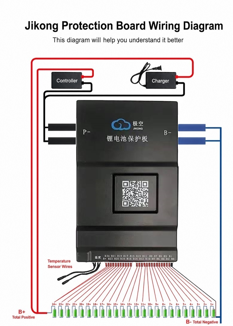
Connecting the BMS Power Cables
In many systems, the BMS is installed on the negative side of the battery.
A simplified circuit looks like this:
negative of the LiFePO4 pack → BMS → external battery negative.
With this configuration, the positive power terminal is connected directly to the final positive terminal of the battery pack.
Common BMS terminal markings include:
B− — connection directly to the negative terminal of the battery pack;
P− — negative power terminal for the load.
Some BMS models provide a separate negative terminal for the charger.
Therefore, always follow the wiring diagram for the specific BMS being used.
Installing Temperature Sensors
A BMS may use one or more temperature sensors.
They monitor the temperature of the battery cells and other system components.
The sensors must be securely attached to the surfaces being monitored.
The wiring should be routed so that it:
does not pass underneath the busbars;
is not pinched by the enclosure;
does not touch sharp metal edges;
cannot be accidentally pulled out.
If the temperature exceeds the configured limits, the BMS may disable battery charging or discharging.
First Battery Startup
After connecting the BMS, the first complete system check can be performed.
Modern Bluetooth-enabled BMS units allow battery parameters to be monitored through an application.
Check:
total voltage;
voltage of each cell;
number of detected cells;
temperature;
charging current;
discharge current;
protection status;
balancing status.
Pay particular attention to the individual cell voltages.
All values should be within the expected range.
Checking Cell Voltage Difference
For a battery pack, the total voltage is not the only important parameter.
The difference between the highest-voltage and lowest-voltage cells must also be monitored.
For example:
maximum voltage — 3.340 V;
minimum voltage — 3.330 V.
Difference:
3.340 − 3.330 = 0.010 V, or 10 mV.
The smaller the difference under the same conditions, the more evenly the cells are operating.
Large differences are particularly noticeable near the upper and lower ends of the state-of-charge range.
Cell Balancing
Even identical LiFePO4 cells gradually begin to differ slightly from one another.
One cell may charge faster while another charges more slowly.
If one cell reaches the configured upper voltage limit first, the BMS may stop charging the entire battery even though the remaining cells are not yet fully charged.
Balancing is used to reduce these differences.
Passive Balancing
Excess energy from the highest-voltage cells is dissipated as heat through resistors.
Active Balancing
Energy can be redistributed between cells.
For high-capacity batteries, balancing performance is particularly important because a small balancing current will correct a significant imbalance very slowly.
BMS Configuration
After the first startup, the battery management system settings should be checked.
Depending on the BMS model, available parameters may include:
number of cells;
battery capacity;
maximum cell voltage;
minimum cell voltage;
maximum battery voltage;
minimum battery voltage;
maximum charging current;
maximum discharge current;
temperature cutoff;
balancing activation threshold;
permitted voltage difference between cells.
Unless necessary, operating parameters should not be set directly at the absolute limits of the LiFePO4 cells.
For stationary systems, slightly limiting the usable charge and discharge range is generally beneficial for extending battery service life.
Calculating Battery Current for an Inverter
One common mistake is selecting a BMS based only on battery capacity.
When operating with an inverter, the load power must also be considered.
The approximate relationship is:
current = power / voltage.
For example, if an inverter draws 2000 W from a battery operating at approximately 25 V:
2000 / 25 = 80 A.
This is an approximate calculation that does not include losses.
The actual current drawn from the battery will be somewhat higher.
At 3000 W:
3000 / 25 = 120 A.
Therefore, even relatively moderate inverter power can result in very high currents in a low-voltage system.
This must be taken into account when selecting:
the BMS;
power cables;
cable lugs;
fuse;
circuit breaker;
connectors;
power terminals.
Selecting and Connecting Power Cables
Power cable cross-section should be selected according to the maximum operating current, cable length, installation method, and acceptable voltage drop.
Insufficient conductor size increases resistance.
This can result in:
voltage drop;
cable heating;
energy losses;
heating at connection points;
possible inverter shutdown under heavy load.
Particular attention should be paid to the quality of cable lug crimping.
At high currents, a poorly crimped lug can become significantly hotter than the cable itself.
Installing the LiFePO4 Battery in an Enclosure
After checking the electrical system, the battery can be installed in its enclosure.
The enclosure should:
protect the cells;
prevent accidental access to current-carrying parts;
securely hold the battery cells;
provide reliable mounting for the BMS;
allow the power terminals to be safely routed outside.
All heavy components must be mechanically secured.
A power cable or electrical connector should never be expected to serve as a mechanical mounting point.
Insulating the Busbars
After completing all electrical connections, exposed current-carrying parts should be protected.
The top of the battery is particularly hazardous because many terminals and connecting busbars are located close together.
A metal object accidentally dropped onto the battery can short-circuit several cells.
It is therefore advisable to use:
protective covers;
insulating plates;
heat-resistant insulating materials;
terminal protection.
After assembly, no loose nuts, washers, or other metal objects should remain inside the enclosure.
Installing External Power Connectors
For convenient inverter connection, power terminals can be mounted directly on the battery enclosure.
These may include:
power terminals;
bolted terminals;
high-current quick-disconnect connectors.
The connector and contacts must be rated for the maximum battery current.
Before connecting the inverter for the first time, always check the polarity of the external connector with a multimeter.
Do not rely solely on wire colors.
Battery Status Indicator
An additional display can be installed on the enclosure.
It may show:
voltage;
current;
approximate state of charge;
load power;
charging or discharging mode.
[PHOTO 11 — external battery display]
Such an indicator is convenient for everyday use.
For diagnosing individual cells, data directly from the BMS is more useful.
Battery Protection
A high-capacity LiFePO4 battery is a powerful energy source.
The BMS should not be considered the only protective device in the entire electrical system.
Appropriate fault-current protection should be installed in the power circuit.
It must be selected according to:
battery DC voltage;
normal operating current;
possible surge currents;
cable characteristics;
inverter specifications.
The protective device should preferably be installed as close to the battery as practical.
This protects not only the inverter but also the power cable between the battery and the equipment.
Inverter Precharge
Powerful inverters contain capacitors at their DC input.
If fully discharged input capacitors are connected directly to the battery, a very high current pulse may occur at the moment of connection.
This can produce a spark at the contacts and place additional stress on connectors and the BMS.
Some battery systems therefore use a precharge circuit.
It allows the inverter's input capacitors to charge first through a current-limiting resistance before the full power connection is made.
Final Battery Check
Before connecting the battery to the hybrid inverter, the entire assembly should be checked again.
Electrical System
Check:
total voltage;
polarity;
voltage of each cell;
cell voltage difference;
correct BMS connection;
power connections.
Mechanical System
Check:
cell securing;
BMS mounting;
power cable securing;
absence of loose parts;
absence of conductor contact with sharp edges.
BMS
Check:
number of cells;
cell voltages;
temperature;
protection parameters;
maximum current;
balancing settings;
configured battery capacity.
[PHOTO 12 — fully assembled LiFePO4 battery]
First Charge and Discharge
After connecting the battery to the system, its behavior should be carefully monitored during the first operating cycles.
Monitor:
battery voltage;
individual cell voltages;
charging current;
discharge current;
temperature;
balancing operation;
protection activation.
Battery behavior near the upper state-of-charge limit is particularly informative.
This is where differences between cells become most noticeable.
If one cell consistently reaches the upper voltage limit significantly earlier than the others, the battery condition and balancing should be checked.
Why LiFePO4 State of Charge Is Difficult to Determine from Voltage
A characteristic feature of LiFePO4 chemistry is its relatively flat discharge curve.
Across a large part of the usable range, the voltage changes only slightly.
Therefore, estimating the remaining state of charge solely from voltage can result in significant errors.
For a more accurate estimate, modern BMS units can measure the current flowing into and out of the battery.
Using the configured battery capacity, the system calculates the approximate amount of energy remaining.
After correct BMS configuration and several operating cycles, this method provides considerably more useful information than voltage measurement alone.
Advantages of a LiFePO4 Battery for a Hybrid Inverter
LiFePO4 technology is well suited to backup power and energy storage systems.
Its advantages include:
long cycle life;
high charging and discharging efficiency;
ability to deliver high currents;
stable operating voltage;
relatively high thermal stability;
no pronounced memory effect;
individual cell monitoring through the BMS;
flexibility in building batteries with different capacities.
These batteries are used with hybrid inverters, solar power systems, backup power installations, and off-grid power systems.
Common Mistakes When Building a LiFePO4 Battery
Incorrect Polarity
One of the most dangerous mistakes.
Before installing each busbar, make sure you understand exactly which terminals it connects.
Incorrect Balance Wire Connection
The BMS connector should not be plugged in until the voltages have been verified with a multimeter.
Accidental Short Circuit
Never place metal tools on top of battery cells.
Loose Power Connections
A poor connection creates additional resistance and may become extremely hot under load.
Insufficient Cable Size
A powerful low-voltage inverter draws considerable current, making proper power wiring especially important.
Incorrectly Selected BMS
Both the number of cells and the maximum charging and discharging currents must be considered.
Lack of Additional Protection
The BMS is part of the protection system, but it does not replace correctly selected protection for the main power circuit.
Poor Mechanical Securing
Cells, the BMS, cables, and connectors should not move freely inside the enclosure.
LiFePO4 Battery Diagram for a Hybrid Inverter
In simplified form, the completed system can be represented as follows:
LiFePO4 cells → connecting busbars → BMS → power protection → power connector → hybrid inverter
Separately connected to the BMS are:
balance wires → each individual cell
and
temperature sensors → battery cells
This allows the BMS to receive information about individual cell conditions while simultaneously controlling the battery's power circuit.
Conclusion
Building a LiFePO4 battery for a hybrid inverter requires careful attention at every stage.
First, the battery cells and their voltages must be checked. The cells are then arranged in the correct sequence and connected using busbars.
Next, the balance wires, BMS power connections, and temperature sensors are connected.
Before installing the battery in its enclosure, make sure that the BMS correctly detects all cells and displays the correct total voltage.
Power cables, high-quality cable lugs, reliable insulation, and protection of the power line between the battery and inverter are equally important.
After final assembly, check polarity, total voltage, individual cell condition, and BMS parameters.
When assembled correctly, the result is a complete LiFePO4 energy storage battery that can be used with a compatible hybrid inverter in a backup or off-grid power system.
Write a comment